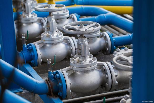
The centrifugal pump is arguably the most widely used piece of rotating equipment in modern industry. From delivering clean drinking water to municipal households, to circulating chilled water in high-rise HVAC systems, and powering large-scale agricultural irrigation networks — centrifugal pumps are the silent workhorses that keep civilization moving.
But what exactly happens inside that cast-iron casing when you press “start”? In this comprehensive explainer, we break down the fundamental working principle of centrifugal pumps, dissect their key components, explore the different configurations available, and teach you how to read a pump performance curve — a skill every engineer and procurement professional should master.
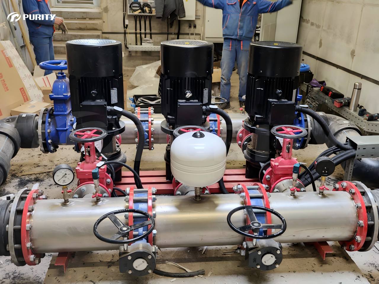
Picture | On-site application of Purity PTD centrifugal pump
1. What Is a Centrifugal Pump? The Basic Principle
At its core, a centrifugal pump is a machine that converts rotational kinetic energy from a motor or engine into hydrodynamic energy to move fluids. The name “centrifugal” comes from the centrifugal force that drives the liquid outward from the center of rotation.
Think of it like spinning a bucket of water around your body — the water is pushed outward by the force of the spin. A centrifugal pump uses this same physical principle, but in a precisely engineered, highly efficient manner.
The Working Principle Step by Step:
1.Priming: The pump casing is filled with liquid before startup (centrifugal pumps cannot pump air).
2.Suction: As the impeller rotates at high speed (typically 1,450–3,600 RPM), it creates a low-pressure zone at the suction eye, drawing fluid into the center of the pump.
3.Energy Transfer: The impeller vanes (blades) spin the liquid outward, transferring kinetic energy from the motor to the fluid.
4.Conversion to Pressure: The liquid enters the volute casing — a gradually expanding spiral channel — where its high velocity is converted into high pressure (Bernoulli’s principle).
5.Discharge: The pressurized fluid exits through the discharge nozzle and enters the pipeline system.
2. The Seven Key Components of a Centrifugal Pump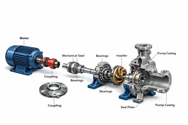
Figure | Exploded view of a centrifugal pump
Understanding the anatomy of a centrifugal pump is essential for troubleshooting and maintenance. Below are the seven core components that make up every standard design:
| Component | Function |
| Impeller | The rotating disc with curved vanes that transfers energy to the fluid. Available in closed, semi-open, and open designs. |
| Volute Casing | The spiral-shaped housing that collects fluid from the impeller and converts velocity into pressure. |
| Shaft | The steel rod connecting the motor to the impeller, transmitting torque. |
| Mechanical Seal | A precision-engineered sealing device that prevents fluid from leaking along the shaft. |
| Bearings | Support the shaft and maintain precise impeller alignment under load. |
| Wear Rings | Replaceable rings on the impeller and casing that minimize internal leakage and protect the main components from wear. |
| Coupling | Connects the pump shaft to the electric motor or diesel engine shaft. |
3. A Quick Overview of Centrifugal Pump Types
Different applications demand different pump configurations. Here are the four most common types you will encounter in industrial settings:
(1) End Suction Centrifugal Pump: The most widely produced design. Fluid enters from the end of the casing and exits at the top. Ideal for general water supply, HVAC circulation, and light industrial transfer.
(2) Horizontal Split Case Pump: The casing splits horizontally along the shaft axis for easy maintenance. Designed for high-flow applications like municipal water treatment plants and large-scale cooling systems.
(3) Multistage Centrifugal Pump: Contains two or more impellers arranged in series within a single casing. Each stage adds pressure, making this design essential for high-head (high-pressure) applications such as boiler feed water and high-rise building water supply.
(4) Vertical Inline Centrifugal Pump: The suction and discharge nozzles are aligned along the same axis, allowing the pump to be installed directly into a pipe run — saving valuable floor space in mechanical rooms.
4. How to Read a Centrifugal Pump Performance Curve
A pump performance curve is a graphical chart that shows the relationship between flow rate (Q, typically in m³/h or GPM) and head (H, in meters or feet). Knowing how to read this curve is critical for system design.
Key elements on a standard curve:
(1) Flow vs. Head Curve: As flow increases, the head (pressure) decreases. This curve tells you how much pressure the pump will deliver at any given flow rate.
(2) Best Efficiency Point (BEP): The specific flow rate where the pump operates at its highest hydraulic efficiency — typically 70%–85% for modern designs. Running a pump close to its BEP minimizes energy consumption and mechanical stress.
(3) NPSHr Curve: Net Positive Suction Head Required. This indicates the minimum suction pressure needed to prevent cavitation — a destructive phenomenon where vapor bubbles form and collapse inside the pump, eroding the impeller.
(4) Power Curve: Shows the motor power (kW or HP) consumed at different flow rates.
5. Frequently Asked Questions (FAQ)
Q: Why can’t a centrifugal pump run dry?
A: Centrifugal pumps rely on the pumped liquid for both cooling and lubrication of the mechanical seal. Running dry — even for a few seconds — can cause the seal faces to overheat and fail catastrophically.
Q: What is the difference between an open and a closed impeller?
A: A closed impeller has shrouds (side walls) on both sides of the vanes, offering the highest efficiency for clean liquids. An open impeller has no shrouds, making it suitable for fluids containing solids or debris, but with lower hydraulic efficiency.
Q: How do I prevent cavitation in my system?
A: Ensure the pump’s Net Positive Suction Head Available (NPSHa) exceeds the pump’s required NPSH (NPSHr) by a safety margin. Common solutions include lowering the pump elevation relative to the supply tank, increasing suction pipe diameter, or reducing fluid temperature.
Partner with a Global Leader in Centrifugal Pump Technology
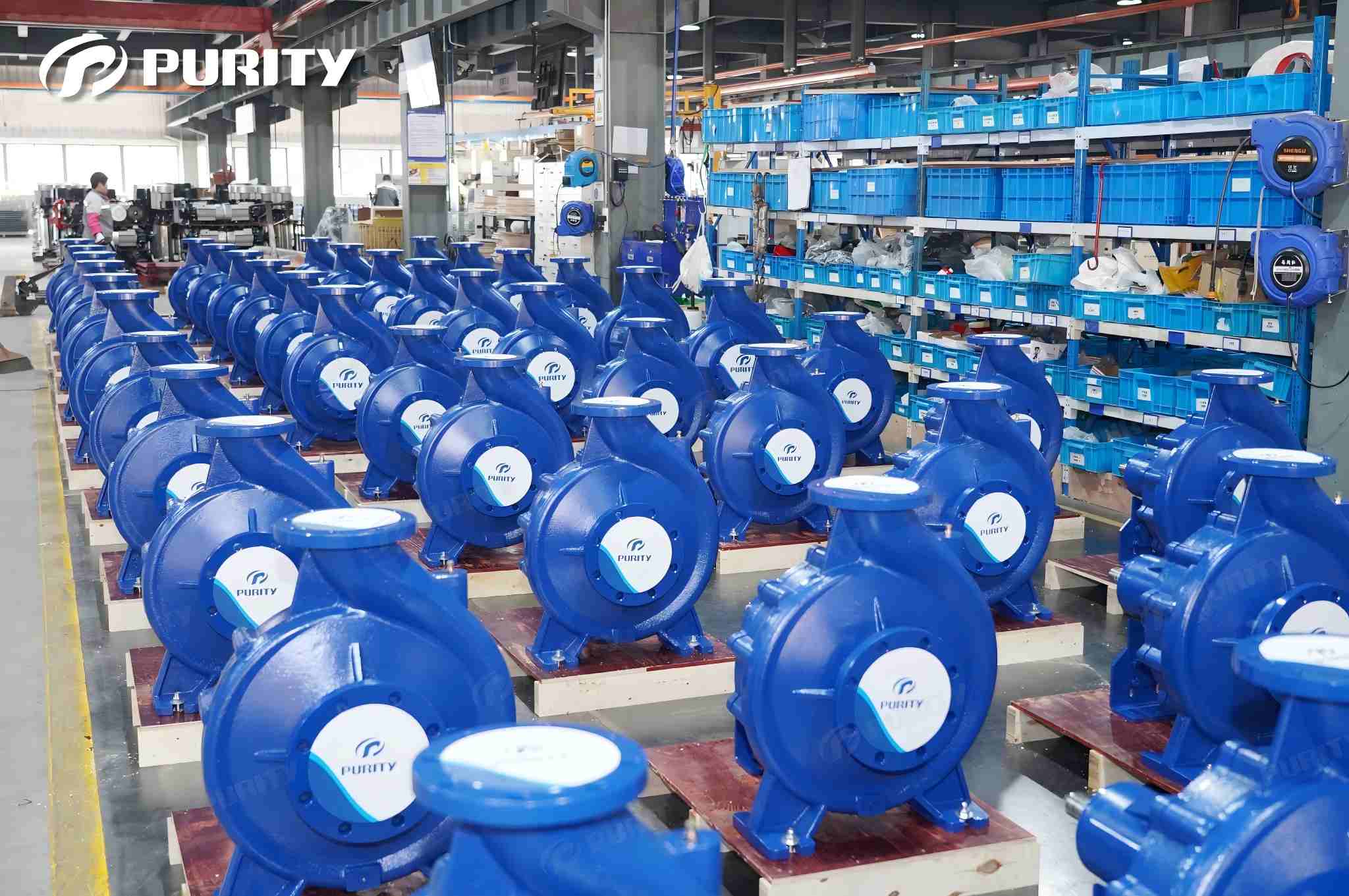
Picture | Purity end-suction centrifugal pump – in-stock at the factory
At Purity Pump, we design and manufacture ISO-certified industrial centrifugal pumps that operate at peak efficiency across more than 130 countries. Whether you need a standard end suction pump for a commercial building, a split case pump for a municipal water treatment plant, or a custom multistage solution for a high-rise tower, our engineering team has the expertise to specify the right pump for your system.
Contact Purity Pump today to request a performance curve analysis, CAD model, or custom quote for your next project.
Post time: Jul-15-2026